|
|
Building robots instead of sleeping... |
|
|
Building robots instead of sleeping... |
Home
Projects
Shop
Forums
Download
About JRO Other
|
EyeBo - The Line Following Robot |
Overview
I built Eye-Bo so that I could compete in the
annual line-following contest that Chibots
holds each year. They actually run two different line-following contests,
basic and advanced. I competed in both, and won the advanced line-following
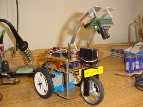
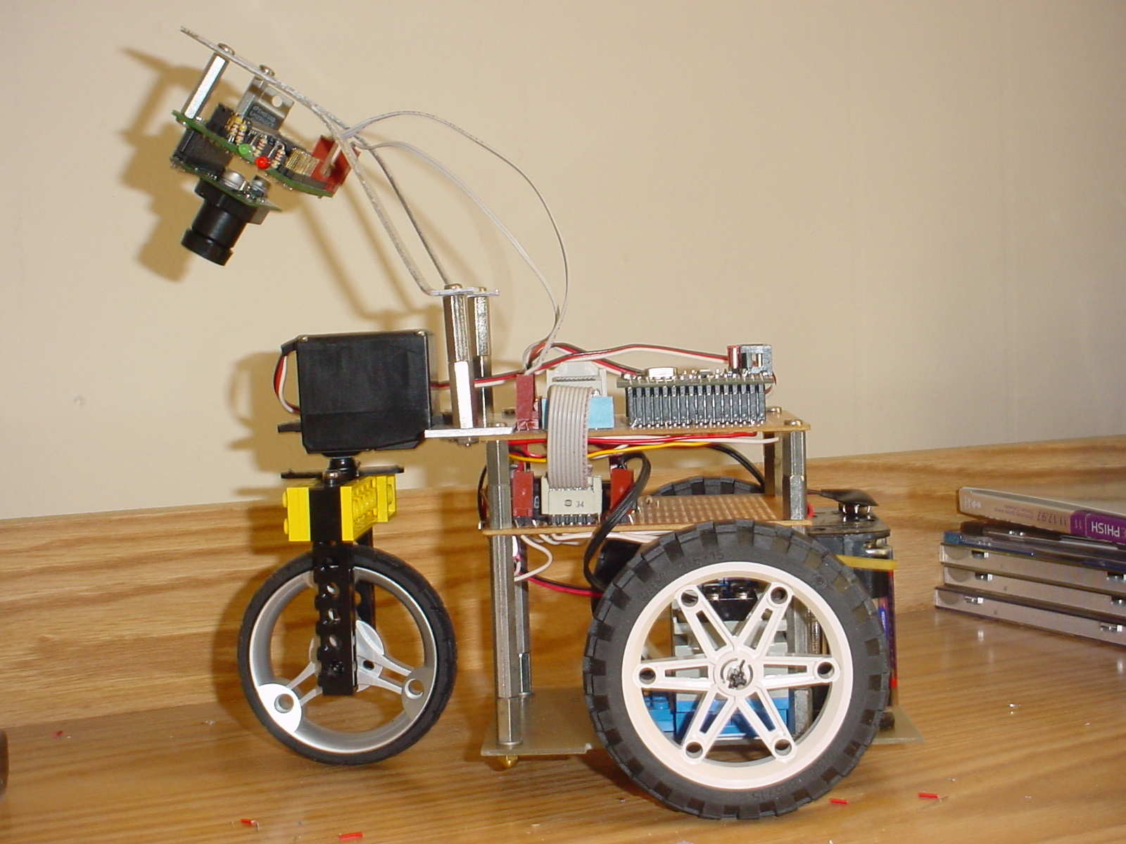
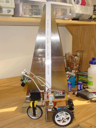
contest both times I entered. The pictures of EyeBo 2 can be seen below.
 |
 |
NEW November 2004 For the November 2004 Chibots line-following contest, I decided to update the design and add some new features. Namely, I replaced the CMUcam with the AVRcam, re-wrote the line-tracking software, and modified how the camera connects to the board. It ended up being a MUCH better design all the way around!
NEW JANUARY 2005 Finally adding a link to the night-before-the-contest test run video of Eye-Bo 3 with the AVRcam guiding it.
Electrical
Eye-Bo's brain is a small microcontroller board
based on Atmel's AVR mega128
microcontroller. This microcontroller is one of the most capable chips I've
ever worked with, sporting 128K of flash program space and 4K of RAM. I was
running the mega128 at 14.7 MHz to make sure there would be plenty of processing
power. I really like the AVR family of microcontrollers, and turn to them
whenever I need a brain on my bot.
The main sensor I used to track the line is the CMUcam vision sensor. This sensor can track a single colorful object at 16.7 frames/sec. I used the sensor two different ways (at two different contests) to perform the line following function. The first used the line-mode of the CMUcam, whereby all pixels that matched the color of the line being followed were reported up to the mega128 board. Then, the line info was processed by the mega128 to determine if the line was going straight, curving to the right, or curving to the left. Once the line info was processed, a servo motor used to steer the bot was driven to center the line over the bot.
The second, simpler way I used the CMUcam was to simply have it report the centroid of the white objects it sees (again, the line was white). Thus, if the line curved to the right or left, the centroid shifted as well. The centroid could then be used as an indicator to determine how the steering servo should be driven. Both methods worked well, though the latter was much simpler to get working.
NEW November 2004
Eye-Bo 3 uses the AVRcam to detect the line visually at 30 frames/sec processing speed. The AVRcam is trained on the white line, and can distinguish it easily from the black background. The AVRcam breaks the line up into 8 different chunks, and reports back the coordinates of each chunk through a serial port to the mega128. These chunks define how the line appears to the robot, and allows it to make decisions about how to drive the steering servo motor.
In addition to the main controller board with the mega128, I also had a motor driver board which contained the two H-bridges to drive the two Lego motors which propelled the robot forward.
Software
I developed the software using the GCC C compiler
for the AVR. I use this compiler for almost all of my AVR projects (unless I
need to dip down into Assembly, which isn't often luckily). The majority of the
code (which only ended up being around 3K) was dedicated to processing the
line. There was also code to determine the angle of the steering servo motor,
as well as the speed of the two Lego drive motors.
Mechanical
There wasn't too much mechanical work on this
robot. I used two of the standard geared Lego motors to propel the robot. A
single standard servo is located at the front of the robot to steer the bot.
This arrangement works much better for line following compared to the standard
dual-drive setup where the robot turns by reversing the direction of one of the
motors..
The two Lego motors are actually connected to each other with standard Lego pieces, and then secured to the base of the robot with regular screws. This setup works well, since it allowed me to play with different Lego wheels during development ( I ended up using the standard 3" Lego wheels in the end, which allowed the robot to travel at around 3 feet/second when running straight ahead.
NEW November 2004
The AVRcam was attached to the steering servo instead of
being mounted to the robot body itself. This enabled the control loop running
on the mega128 to execute better since the camera was able to see whatever the
steering servo was pointing at.
The Contest
I had actually taken the Friday before the first
contest off of work to try to get the robot as functional as possible. I had
pretty mediocre success at home when testing it. The bot always seemed to see a
patch of sunlight, or some other light object and went darting off for it
instead of staying on the course I had rigged up. But I figured that even if it
only made it around half a lap it would be worth trying.
The basic line following contest involves black squares that contain either a straight or a 90-degree curved white line. The squares are put together the day of the competition to form a course. An example of the basic course is shown below.
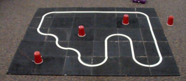
Eye-Bo did pretty good on this course, until it reached big "S" in the course in the lower right of the photo. The problem? As the bot was trying to take the turns, it would look ahead and see another portion of the white line, and headed for it instead of staying on the course in front of it. This happened every time it ran, and thus wasn't able to successfully complete a single lap. I tried to "argue" that Eye-Bo was simply "optimizing" its solution to the course, but this didn't fly. Oh well...With more time, I may have been able to get the code to stick to the line, but I had to get ready for the advanced line following contest, which was next.
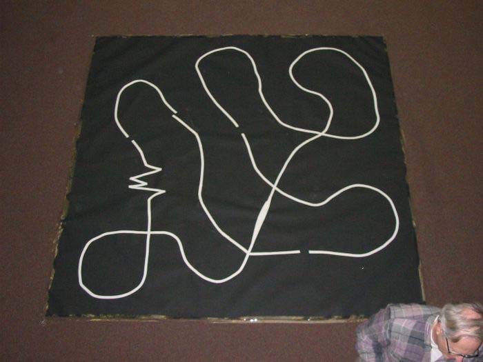
The advanced line following contest course is comprised of a white line on a black background that zigs and zags around, crossing itself, looping, and even contains breaks in the line. An example of the course is shown below.
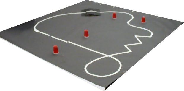
It turned out that this course was easier for Eye-Bo to navigate because there weren't any sections where the potential existed to dart off to a different portion of the course like in the basic contest. Tracking the line visually ended up being a huge benefit here, because the bot was able to legally "optimize" portions of the course such as the zig-zag, and could basically zip right through it. This section caused the most problems for the other bots. I did have to take a small penalty because my bot wasn't able to make it up the hill on the course (shown at the top of the photo). I ended up winning this competition (see the cool trophy that Terry Surma made for the contest below).
NEW November 2004
The advanced line following course was much different for this contest (the guy who put the course together told me he was hoping to give EyeBo a "challenge"). A picture of the course can be seen below:
EyeBo 3 did pretty good on the course, though there were a couple of places where it got confused. As I said before, the control algorithm was much better this time, allowing for more accurate tracking of the line. I was still playing with different ways of using the tracked-line information to drive the servo, and know that the code I ran the course with was far from optimal. I'm hoping to tweak it a bit and be ready for the next contest in the Spring of 2005. Congratulations to Steve Hassenplug who won first place...too bad it'll be the LAST time he wins first place :-)
Copyright © 2004 JROBOT All Rights Reserved